They are based on an Arm ® Cortex ®M4 with FPU CPU with 3MB flash and 1MB SRAM Memory scalability is supported with multiple memoryexpansion interfaces, including a HyperBus™/Xccela™ DDR interface and two SPI execute in place Simplified Block Diagram Arm® Cortex®M4 MicrocontrollerTI LM4F230 ARM Cortex™M4 TIVA MCUs Texas Instruments LM4F230 series ARM Cortex™M4 Microcontrollers (MCUs) are TIVA devices featuring Advanced Motion Control, USB OTG, and a high number of serial communication peripherals, including up to 8Arm® Cortex®M4 32bit MCUFPU, up to 64 KB Flash, 16 KB SRAM, ADC, DAC, USB, CAN, COMP, OpAmp, 36 V Datasheet production data Features • Core Arm® 32bit Cortex®M4 CPU with FPU (72 MHz max), singlec ycle multiplication and HW division, DSP instruction • Memories – 32 to 64 Kbytes of Flash memory – 16 Kbytes of SRAM on

Block Diagram Of Cortex M3 Processor Architecture Download Scientific Diagram
Arm cortex m4 block diagram
Arm cortex m4 block diagram-CortexM4 Block Diagram ECE 5655/4655 RealTime DSP 2–13 CortexM4 Block Diagram Optional WIC ARM CortexM4 Microprocessor Nested Vector Interrupt Controller (NVIC) Optional Debug Access Port Optional Memory protection unit Bus matrix Code interface SRAM and peripheral interface Optional FPU Processor coreThe PSoC 63 programmable line of microcontrollers features an Arm CortexM4 processor and an Arm CortexM0 processor, onchip Bluetooth Low Energy, lowpower flash technology, digital programmable logic, highperformance analogtodigital
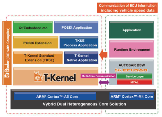


Freescale And Esol To Collaborate On Software Solutions For Vybrid Automotive Devices 新闻公告 Esol的嵌入式软件方案
29/7/19 · The ARM architecture processor is an advanced reduced instruction set computing RISC machine and it's a 32bit reduced instruction set computer (RISC) microcontroller It was introduced by the Acron computer organization in 1987 This ARM is a family of microcontroller developed by makers like ST Microelectronics,Motorola, and so onThe 32bit Arm® Cortex®M4 processor core is the first core of the CortexM line up to feature dedicated Digital Signal Processing (DSP) IP blocks, including an optional FloatingPoint Unit (FPU)It addresses digital signal control applications that require efficient, easytouse control and signal processing capabilities, such as the IoT, motor control, power management, embeddedWe have launched Study Focus and Sleep Music Android Mobile App *** No Ads at All ***https//playgooglecom/store/apps/details?id=commbreathsleeptherapyn
ARM Simplified Block Diagram System on Chip (SoC) ARM CortexM4 Organization (STM32L4) 12 Systemonachip Instructions System Bus I n t e r r u p t A C o n t r o l l e r n (N V I C) Memory Protectionf Unit(MP ) Instruction Bus D at Bus Interrupts ` M e m o r y e I n t e r a c Cort exM4P c s7/8/16 · Arm arc16 1 ARM Zero To Hero Level IBy Mohammed Gomaa 2 ARM Architectures ARM CortexM4F 3 Road Map ARM Architectures and Processors o What is ARM Architecture o ARM Processor Families o ARM CortexM Series o CortexM4 Processor ARM Processor vs ARM Architectures o ARM CortexM4 Processor o CortexM4 Processor Overview o CortexM4 Block Diagram o CortexM4Simplified Block Diagram Similar products you might be interested in Exact equivalent in functionality and parametrics to LowPower ARM CortexM4 with FPUBased Microcontroller with Bluetooth 5 for Wearables MAX LowPower ARM CortexM4 with FPUBased Microcontroller with Bluetooth 5 for Wearables Technical Docs Document Type
Figure 23 The functional block diagram for the ARM ® Cortex ® M4 MCU Interrupt Controller Trace Interface Debug I nterface JTAG/SWD Interrupts ICode & DCode (Flash) & (SRAM) RAM Peripherals SysTick Trace Interface CortexM4 Processor Architecture •32 bit processorThe Arm Corstone102 provides a flexible reference design and system IP for small, lowcost, and energyefficient SoCs Based on the Arm CortexM23 processor, the Corstone102 is targeted for use in small and constrained IoT applicationsThe Arm Corstone101 contains a reference design based on the CortexM3 processor and other system IP components for building a secure system on chip Corstone101 also contains the CortexM System Design Kit which provides the fundamental system elements to design an SoC around Arm processors


Arm Cortex M Wikipedia


Controller Area Network Projects With Arm And Arduino By Elektor Issuu
11/6/21 · ARM Keil Studio Cloud seems to be very broken Not Answered 1 day ago How to prepare tflite for vela compiler?PSoC® 61 Microcontrollers Arm® Cortex®M4 The PSoC 61 programmable line of microcontrollers, based on the PSoC 6 MCU platform, is a highperformance microcontroller with lowpower flash technology, CapSense® capacitive sensing, highperformance analogtodigital, and standard communication and timing peripheralsThis video presents the basics of the CortexM architecture from the programmer's point of view, including the registers and the memory map


Cortex M4 Technical Reference Manual


Cortex M4 Technical Reference Manual
ARM CortexM4 168 MHz Nested vector interrupt controller (NVIC) MPU JTAG/SW debug/ETM Block diagram Floating point unit (FPU) Notes 1 HS requires an external PHY connected to the ULPI interface 2 Crypto/hash processor on STM32F417 and STM32F415 Analog 3x 12bit ADC 24 channels / 244 MSPS 2channel 2x 12bit DAC Temperature sensor Up to 1CortexM4 Block Diagram Nested Vectored Interrupt Controller (NVIC) Up to 240 interrupt request signals and a nonmaskableinterrupt (NMI) Automatically handles nested interrupts, such as comparing priorities between interrupt requests and the current priority level19/8/ · In the last tutorial, we have discussed the indepth introduction of the systick timer module of TM4C123 ARM Cortex M4 microcontroller In that tutorial, Systick Interrupt Block Diagram If you see the interrupt vector table of TM4C123, the
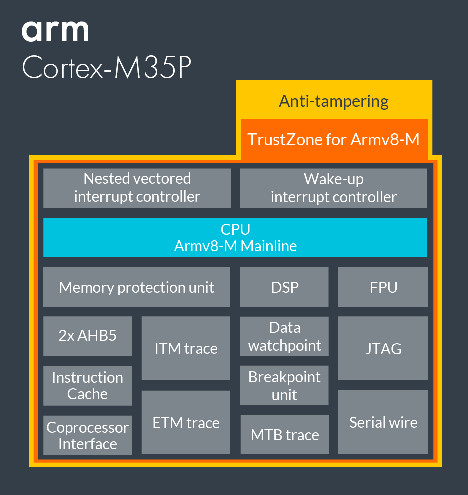


Arm Adds Security To Cortex M For Smart Meters


What Is Arm Architecture And List Types Of Cortex M Series Ssla Co Uk
Microcontrollers For the actual block diagram relevant for any derivative of the TMS570LS series or for the RM4x series of microcontrollers, see the devicespecificdata sheet Figure 1 Device Block Diagram 2 Initialization of the TMS570LS043x, TMS570LS033x and RM42L432 SPNA163– September 12 Hercules ARM CortexR4Microcontrollers SubmitSimplified Block Diagram MAX LowPower, Arm CortexM4 Processor with FPUBased Microcontroller and Bluetooth 52 wwwmaximintegratedcom Maxim Integrated 2The block diagram includes a colorcodedrepresentation of the individual corepowerdomains implemented on the microcontroller (see Figure 2) These power domains can be individually turned ON or OFF during initialization as per the application requirements Figure 2 Color Legend for Block Diagram 2 Initialization of Hercules™ ARM® Cortex


Max Arm Cortex M4 Microcontroller Maxim Mouser
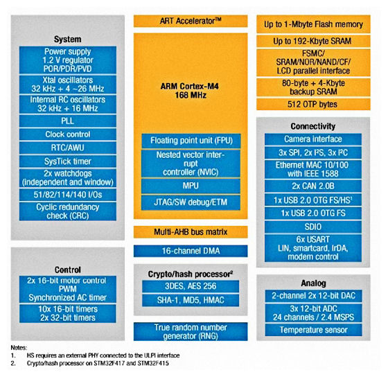


Ingenious Architectural Features Allow St To Extract Maximum Performance From New Microcontroller Family Based On Arm Cortex M4 Cost Less Than 6 Bucks In 1000s Eda360 Insider
31/5/21 · Arm CortexM4 The CortexM4 processor is developed to address digital signal control markets that demand an efficient, easytouseSimplified Block Diagram RSTN MAX–MAX BUS MATRIX – AHB, APB, Powered by Arm CortexM4 Processor with FPU for Industrial and IoT Mode MAX/MAX HighReliability, UltraLowPower Microcontroller for Industrial and IoT Low High MAX–MAX POWER OF10/8/16 · CortexM4 block diagram 10 11 CortexM4 Architecture 11 • Programmer model The processors can have privileged and unprivileged access levels • Privileged access level can access all resources in the processor • Unprivileged access level means some memory regions are inaccessible, and a few operations cannot be used
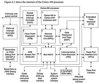


Stm32f407 Microcontroller Sciencezero


Arm Cortex M Family Introduction
CortexM0 Processor ARM Processor Vs ARM Architectures ARM CortexM0 Processor CortexM0 Processor Overview CortexM0 Block Diagram CortexM0 Registers CortexM0 Memory Map CortexM0 Exception HandlingAT32F415 Series Datasheet 310 1 Ver 102 wwwarterytekcom ARM®based 32bit Cortex®M4 MCU with 64 to 256 KB Flash, sLib, USB OTG, 11 timers, 1 ADC, 2 COMPs, 12 communication interfaces FeatureISD ARM® Cortex ®M4F SoC ISD Figure 611 Cortex®M4 Block Diagram 35 Figure 621 ISD Series Power Distribution Diagram 39 Figure 622 SRAM Block Diagram


Cortex M3 Technical Reference Manual
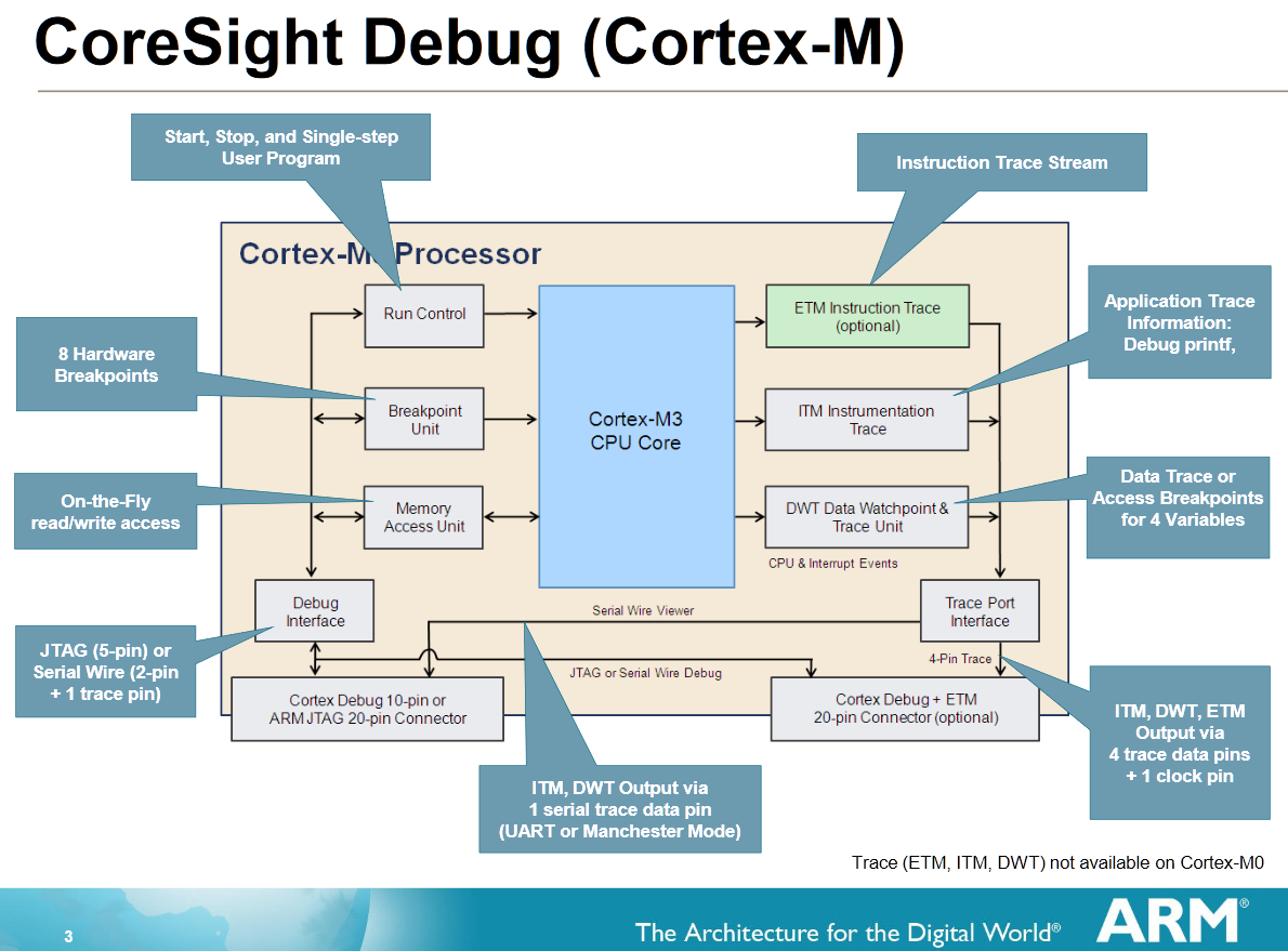


Single Wire Output With The Arm Cortex M And Eclipse Dzone Iot
1 Introduction to Arm CortexM 11 Why learn CortexM system design?22 Block diagram Figure 21 GD32F330xx block diagram e e NVIC m TPIU SW Flash Memory Controller Flash Memory x SRAM Controller SRAM AHB to APB Bridge 2 GP DMA 7chs USART0 SPI 0 ADC TIMER16 12bit SAR ADC IBus ARM CortexM4 Processor F max 84MHz POR/PDR PLL Fmax 84 MHz LDO 12V IRC8M 8MHz HXTAL 432MHz LVD EXTI TIMER0 AHB1 Fmax = 84 MHzControl Processor with ARM CortexM4 Hardware Reference ADC and DAC features and performance specifications differ by processor model Simplified block diagrams of the ADCC, DACC and the ADCs and DACs are shown in Figure 2 and Figure 3 Figure 2 CM402F/CM403F Analog Subsystem Block Diagram DAC1 ADC0 DAC0 ADC1_VIN00 ADC1_VIN01 ADC1_VIN02


New Iot Oriented Cortex M Mcus Add Armv8 And Trustzone


Figure 2 From Using The Arm Cortex M4 And The Cmsis Dsp Library For Teaching Real Time Dsp Semantic Scholar
Based on the ARM CortexM4 Romulo Ant´ ao, Alexandre Mota, Rui Escadas Martins˜ Dept Eletronica, Telecomunicac¸´ oes e Inform˜ ´atica Universidade de Aveiro, Portugal fromuloantao, alex, rmmg@uapt Abstract—The versatility and closedloop performance resulting from the use of selfcalibrating control systems are two ofBlock Diagram NXP iMX8M Quad NXP iMX8M Quad ARM CortexA53 M4 ARM CortexA53 M4 NXP iMX8M Quad ARM CortexA53 M4 Specifications LITE DEV DEVEXTREME ARM CortexA53 M4 4K HDR 275 8500 5600 3607 524 780 160 51 325 2 252 194 MIPI DSI TOUCH PICOPI8M USB Host MIPI Camera MIPI Display MIPI Camera MHF4 PICOIMX8M24/9/14 · The CortexM7's block diagram The Brit CPU designer has today revealed its new 32bit CortexM7 , which will sit at the top of its its microcontrollergrade family of cores in terms of performance The previous cockoftheroost was the CortexM4


Arm Cortex M4 Based Mcus Integrate Lcd Controller Offer Spi Flash Interface Edn


Securing Mcu Designs Digikey
/4/ · Block Diagram of LPC1768 The following image shows the internal block diagram of the LPC1768 MCU As you can see from the block diagram, the ARM CortexM3 Processor consists of three buses Icode bus (for Instruction Fetch), Dcode bus (for Data Access) and System Bus (for peripheral access)Timer Block Diagram, MAX325 ChipDNA Secure Arm Cortex M4 Microcontroller MAX325 ChipDNA Secure Arm Cortex MAX325 10 UART TIMER — UART DeepCover embedded security solutions cloak sensitive data under multiple layers of advanced physical security Arm CortexM4 with FPU ProcessorIntroduction to the Arm CortexM55 Processor By Joseph Yiu, Distinguished Engineer February, White Paper CortexM55 block diagram Here is a quick summary of the key characteristics of the CortexM55 processor 3 (was FPv4 in CortexM4, now FPv5 in recent CortexM processors),
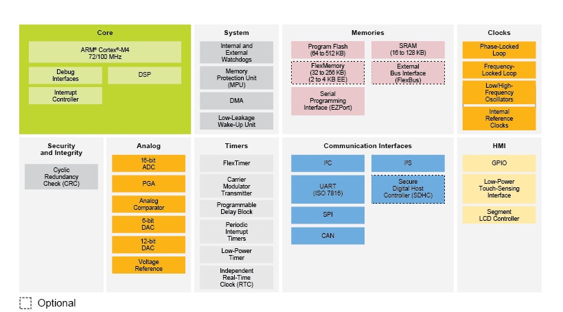


Arm Cortex M4 Kinetis K30 100 Mhz 32 Bit Mcus Nxp Semiconductors
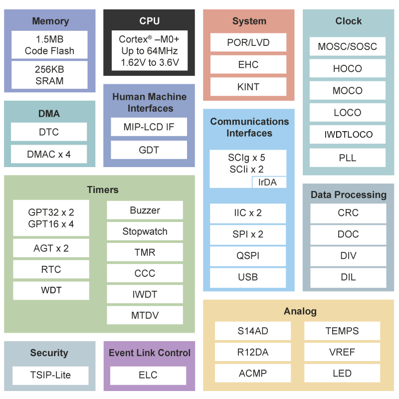


Re Family The World S Most Energy Efficient Mcus With Arm Cortex M Core Electronics Lab Com
The GD32F303xx ®device incorporates the ARM® Cortex M4 32bit processor core operating at 1 MHz frequency with Flash accesses zero wait states to obtain maximum efficiency It provides up to 3072 KB onchip Flash memory and 96 KB SRAM memory An extensive range of enhanced I/Os and peripherals connected to two APB buses14/3/ · SYSTEM FEATURES Up to 240 MHz ARM CortexM4 with floatingpoint unit with ADSPCM41xF Block Diagram SYSTEM CONTROL BLOCKS EVENT CONTROL SYSTEM WATCHDOGS JTAG, SWD, CoreSight™ TRACE PLL & POWER MANAGEMENT FAULT MANAGEMENT SECURITYArquitectura Arm CortexM4 4 Interrupciones 5 C en ensamblador 6 Temporizadores (Timers) 7 GPIO I/O blocks Timer DRAM ctrl FLASH ctrl SRAM ctrl 6 Son dos conceptos distintos Diagrama de bloques CortexM4 (III) 13 REGISTROS EN ARM CORTEXM4
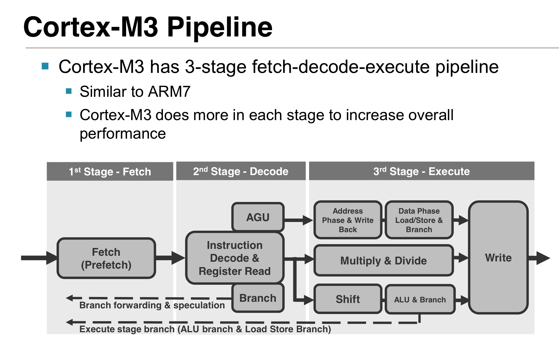


Arm S Cortex M Even Smaller And Lower Power Cpu Cores
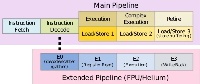


Cortex M55 Microarchitectures Arm Wikichip
2 111 Starting CortexM system design is easy 2 112 CortexM processor systems on FPGA 3 113 Security by design is made easier with Arm architecture 4 12 Understanding different types of Arm processors 4 13 7CortexM deliverablesNot Answered 2 days agoRecommended Products Overview Kinetis V Series MCUs are based upon the Arm CortexM0, CortexM4, and CortexM7 cores and are designed for a wide range of BLDC, PMSM, and ACIM motor control and digital power conversion applications Temperature Sensor


Llvm Cmsis Dsp And Cortex M3 M0 Sushihangover
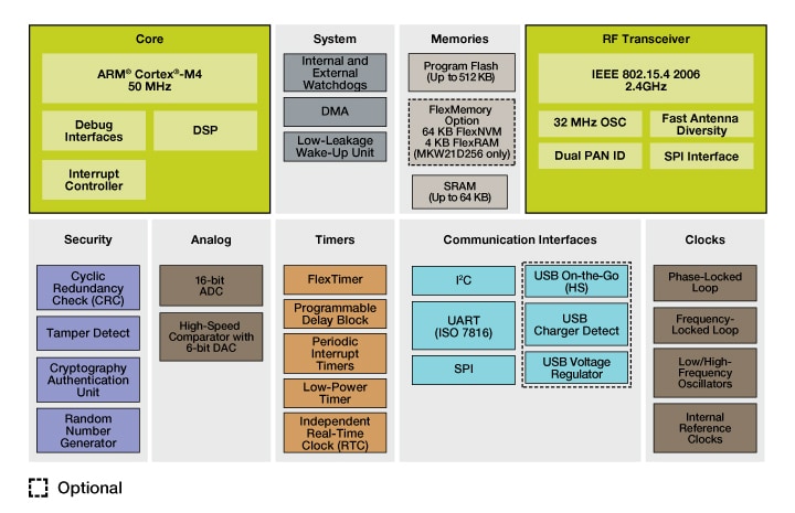


Arm Cortex M4 Kinetis Kw2xd 2 4 Ghz 32 Bit Mcus Nxp Semiconductors
Figure 111 TPIU block diagram 113 Figure 112 TPIU_ACPR bit assignments • ARMv7M Architecture Reference Manual (ARM DDI 0403) • ARM CortexM4 Integration and Implementation Manual (ARM DII 0239)DOCUMENTATION MENU DEVELOPER DOCUMENTATION Back to searchQN9090/30 Block Diagram Features CPU and Memory Up to 48MHz CortexM4 Up to 640 kB flash, up to 152 kB RAM, 128 kB ROM NFC NTAG Option with EEPROM QuadSPI for execute in place or data storage in NVM RF performance/power consumption


Beyond Semi Introduces 32 Bit Ba Core With Cortex M4 Performance Efficiency And Cortex M0 Silicon Area Cnx Software
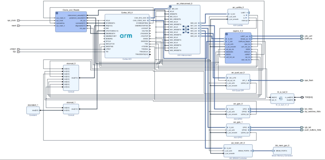


Run Arm Corext M1 Or Cortex M3 On Xilinx Fpga
The iMX 8M family of applications processors based on Arm ® Cortex ®A53 and CortexM4 cores provide industryleading audio, voice and video processing for applications that scale from consumer home audio to industrial building automation and mobile computers Video quality with full 4K UltraHD resolution and HDR (HDR10 and HLG) Highest levels of pro audio fidelity with32bit ARM CortexM4/M0 microcontroller 5 Block diagram Fig 1 LPC43S6x Block diagram ARM CORTEXM4 TEST/DEBUG INTERFACE Icode bus Dcode bus system bus GPDMA LCD system bus SD/ MMC ETHERNET 10/100 MAC IEEE 15 HIGHSPEED USB0 HOST/ DEVICE/OTG HIGHSPEED USB1 HOST/DEVICE EMC HIGHSPEED PHY CORECORE BRIDGE SPIFI HS GPIOThe builtin ARM Cortex M4 core with 64KB RAM and 512KB flash provides a high performance engine and rich interfaces for variety of IoT applications such as sensor network, device control, etc This RF certified Module Block Diagram Ordering Information Applications Author


Arm Unveils Cortex M7 For Smart Devices Industrial Equipment Kitguru


Block Diagram Of Cortex M3 Processor Architecture Download Scientific Diagram


Block Diagram Of Cortex M3 Processor Architecture Download Scientific Diagram


Fast Track Exercises To Understand Arm Cortex M4 Architecture Using Texas Instruments Stellaris Launch Pad Science Publishing Group
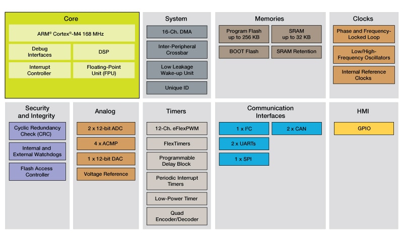


Arm Cortex M4 Kinetis Kv4x Real Time Control Mcus Nxp Semiconductors
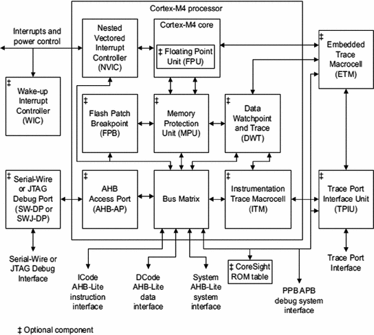


Arm Cortex M4 Core And Tiva C Series Peripherals Springerlink


Psoc 61 Microcontrollers Arm Cortex M4


Verify Fir Filter On Arm Cortex M Processor Matlab Simulink Example Mathworks Nordic
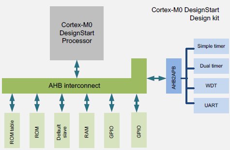


An Introduction To Arm Cortex M0 Designstart


Lpc4300 Cortex M4 M 0 Dual Core Mcus Nxp Semiconductors Mouser
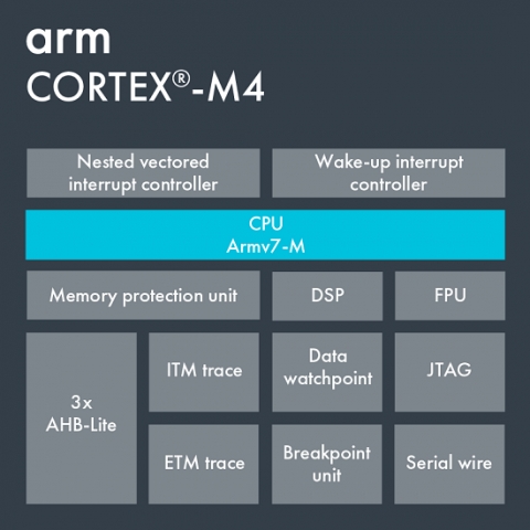


Arm Cortex M4 Ip Core


Fm4 Cy9bfx6xk L Series Motor Control Arm Cortex M4 Microcontroller Mcu Family


How To Transition From Basic Microcontrollers To Arm Cortex Electrical Engineering Stack Exchange
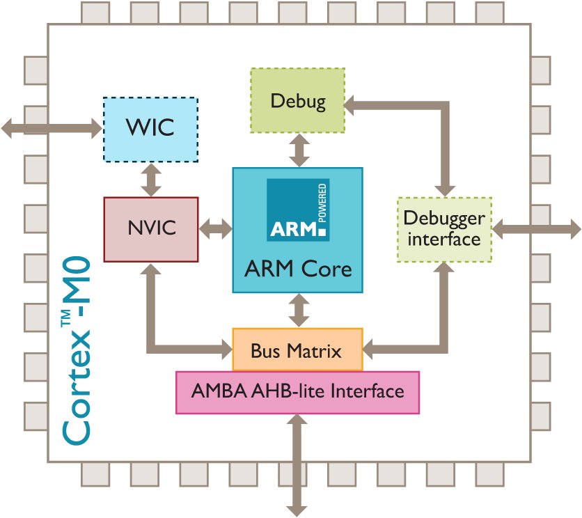


Smallest Lowest Power Arm Core Debuts


How To Transfer Data Blocks 655kb Sec From Cortex M4 To Toradex Community


Stm32h7 Arm Cortex M7 And Cortex M4 Mcus 480 Mhz Stmicroelectronics
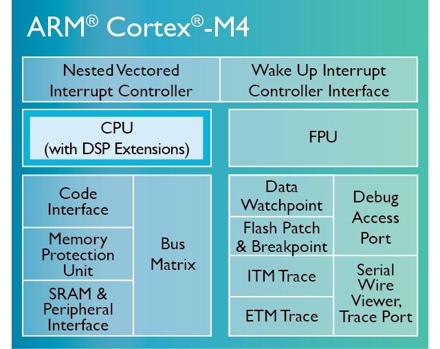


Arm Cortex M4 Architecture Microcontrollers Programming
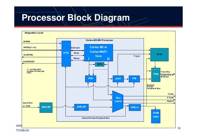


me Arm Techcon13 006v02 Implementation Diversity


Arm Cortex M4 Block Diagram It Eco Map News Navigator


Etm And Itm Swo Trace In Cortex M3 And Cortex M4 Efm32 And Efr32
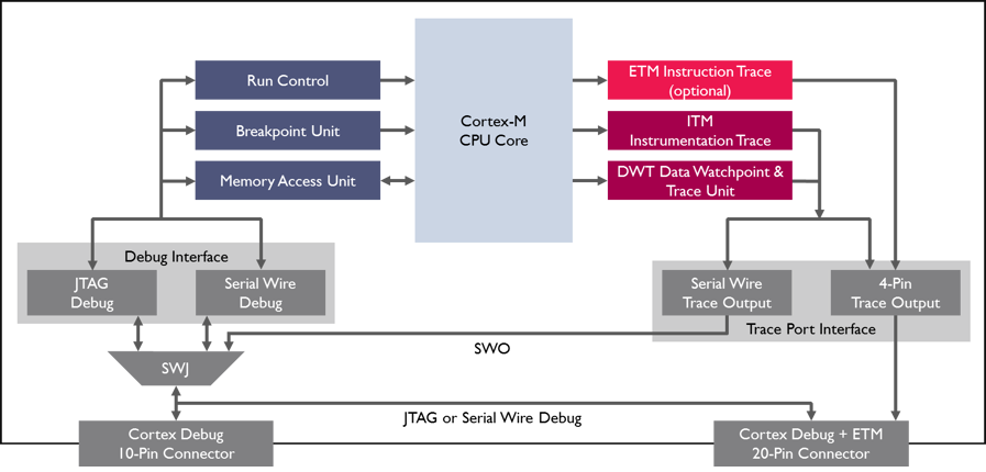


Coresight


Freescale And Esol To Collaborate On Software Solutions For Vybrid Automotive Devices 新闻公告 Esol的嵌入式软件方案


Video Tutorial On Arm Cortex M Series Debug And Trace Youtube


Lpcj512bd64ql Datasheet Low Power 32 Bit Microcontroller Mcu Based On Arm Cortex M4


Arm Cortex M Family Introduction


Register Bank An Overview Sciencedirect Topics


A Block Diagram Of The Module With The Arm Cortex M4 To Analyze Download Scientific Diagram


Max Tiny Ultra Low Power Arm Cortex M4 Processor With Fpu Based Microcontroller Mcu With 256kb Flash And 96kb Sram Maxim Integrated


Psoc 62 Microcontrollers Arm Cortex M4 M0


Register Bank An Overview Sciencedirect Topics


Figure 1 From A Self Tuning Regulator Based On The Arm Cortex M4 Semantic Scholar


Cec1302 Microchip Technology
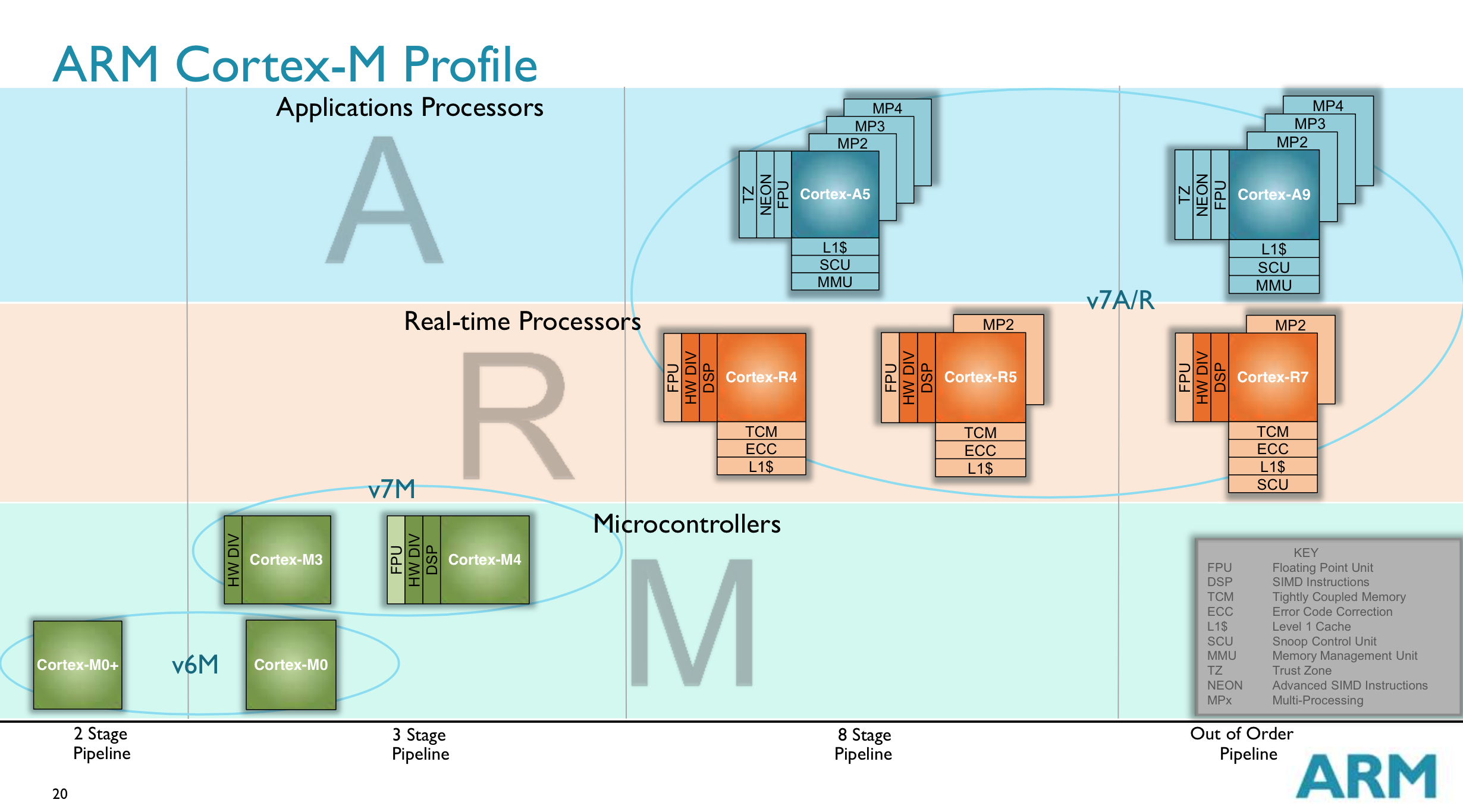


Arm S Cortex M Even Smaller And Lower Power Cpu Cores
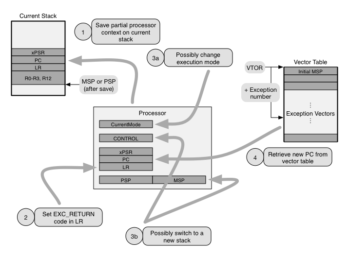


Cortex M Exception Handling Part 2 Ivan Cibrario Bertolotti
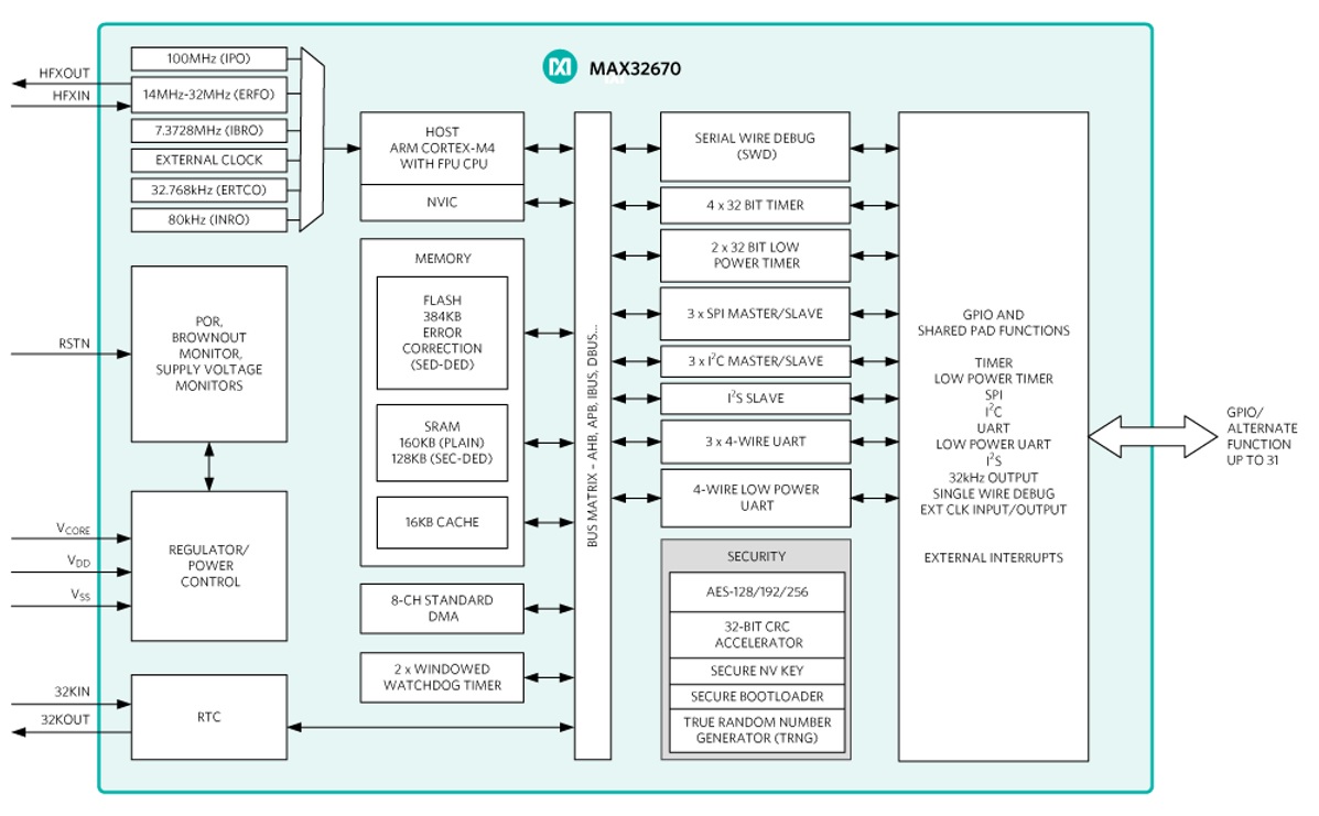


Max High Reliability Ultra Low Power Microcontroller Powered By Arm Cortex M4 Processor Electronics Lab Com


Designing With Arm Cortex M Based Soc Achitectures Part 2 Some Typical Applications Embedded Com


Stm32f401cb High Performance Access Line Arm Cortex M4 Core With Dsp And Fpu 128 Kbytes Of Flash Memory 84 Mhz Cpu Art Accelerator Stmicroelectronics
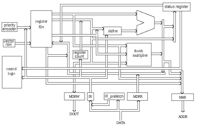


What Is Arm Processor Arm Architecture And Applications


Cortex M4 Arm Developer
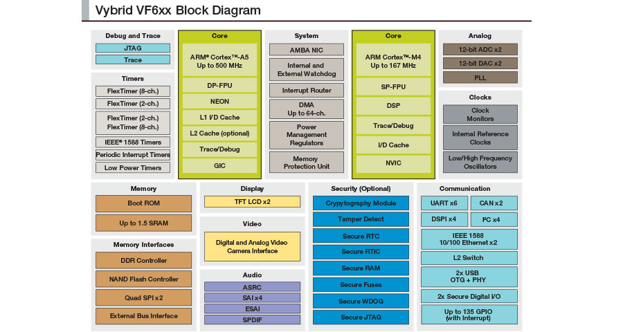


Vybrid Vf6xx Vf5xx Nxp System On Modules Phytec


Rugged Embedded Arm Cortex M Core Those Things 3 3 Born For Ai Ml M55 Programmer Sought
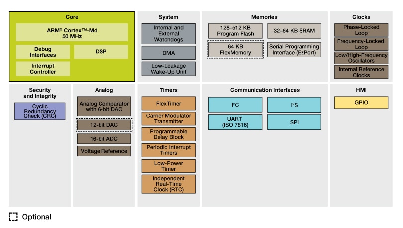


Arm Cortex M4 Kinetis K12 50 Mhz 32 Bit Mcus Nxp Semiconductors


32 Bit Xmc Industrial Microcontroller Arm Cortex M Infineon Technologies


Texas Instruments Introduces New Tiva Arm Cortex M4 Microcontrollers


Raspberry Pi 4 Arm Cortex 2 Processor Sand Software And Sound


Freescale Vybrid Controllers Cortex A5 Cortex M4 Solutions Cnx Software
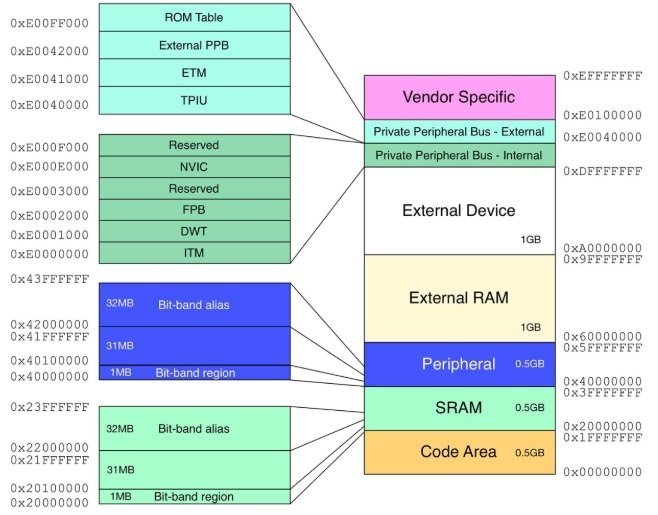


Arm Cortex M4 Architecture Microcontrollers Programming


Arm Cortex M3 Block Diagram Download Scientific Diagram


Arm Cortex M4 Microcontrollers Mouser Argentina
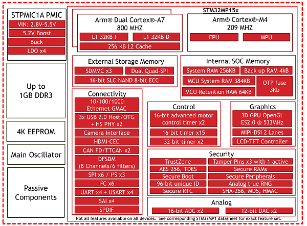


Is There Any Way To Produce Block Diagrams Plantuml Q A


Over The Air Ota Updates In Embedded Microcontroller Applications Design Trade Offs And Lessons Learned Analog Devices
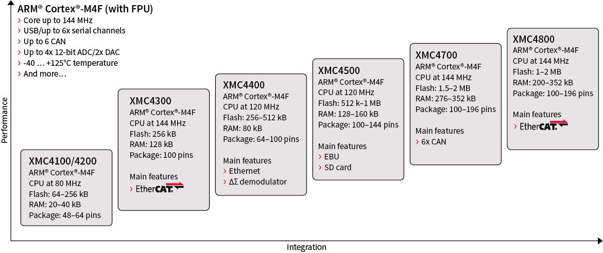


32 Bit Xmc4000 Industrial Microcontroller Arm Cortex M4 Infineon Technologies


Stm 32 F 4 Series Highperformance Cortexm 4
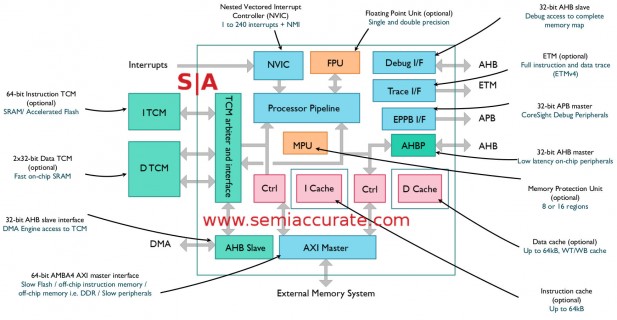


Arm Goes Into Great Detail About The M7 Core Semiaccurate


Systick Timer System Timer Tm4c123g Arm Cortex M4 Microcontroller


Systick Timer System Timer Tm4c123g Arm Cortex M4 Microcontroller Microcontrollers Arm Cortex Timer


Arm Arc 16


Designing With Arm Cortex M Based System On Chips Socs Part I The Basics Embedded Com


Microzed Chronicles Using Cortex M1 And Cortex M Community Forums
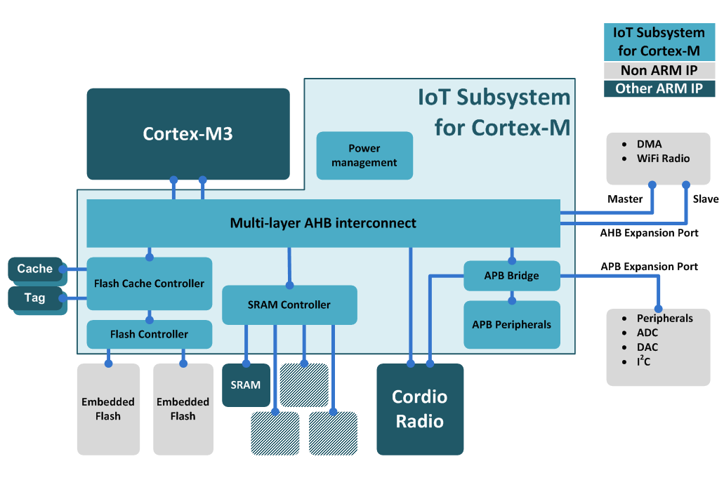


Corelink Sse 100 Iot Subsystem For Cortex M Mbed


Max Ultra Low Power Arm Cortex M4 With Fpu Based Microcontroller Mcu With 3mb Flash And 1mb Sram Maxim Integrated
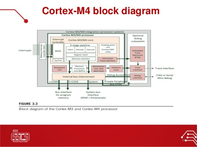


02 Arm Cortex M4 Specs Ieee Sscs Alexsc
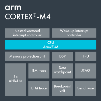


Arm Cortex M4 Microcontrollers Stmicroelectronics


Coresight Etm M4 Technical Reference Manual


Max325 Chipdna Secure Arm Cortex M4 Mcu Maxim Mouser
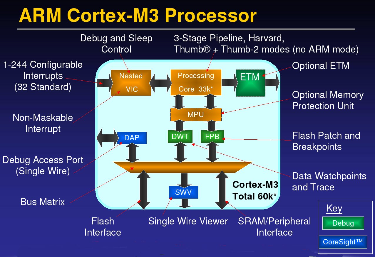


Open Source Arm Cortex Simulator Models Debut


Arm Architecture Wikipedia


Arm Cortex M Family Introduction


Max High Reliability Ultra Low Power Microcontroller Powered By Arm Cortex M4 Processor With Fpu For Industrial And Iot Maxim Integrated


Asymmetric Dual Core Nxp Lpc4300 Microcontrollers Split Tasks Between Arm Cortex M4 And M0 Cores Cost 3 75 And Up Eda360 Insider
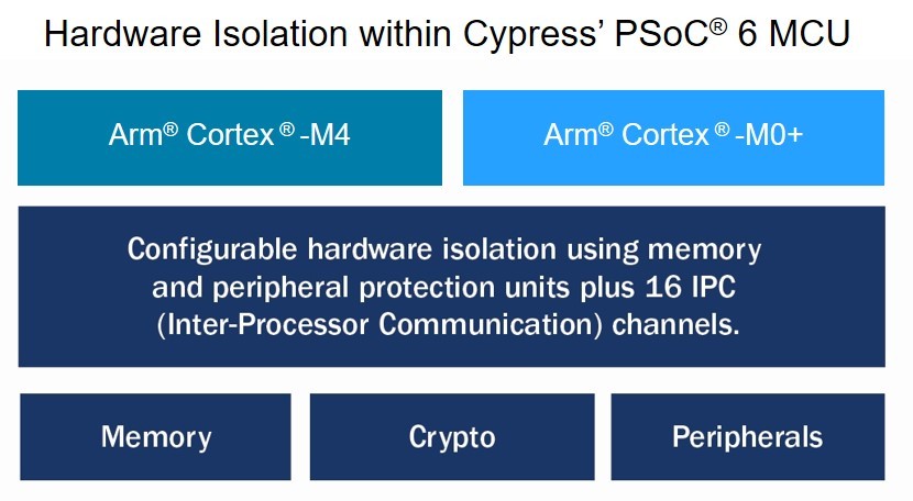


Cypress Accelerates Secure Iot Designs With Support For Platform Security Architecture Trusted Firmware M From Arm Business Wire


0 件のコメント:
コメントを投稿